| TELEFUNKEN E 104 Kw/10 |
|
| Shortwave Communications Receiver |
| Double Conversion Superheterodyne |
| 24 Tubes (23 in first version) + Semiconductors |
| Made in West Germany 1952 - 1965 |
| Specifications | |
| Coverage: | 1.1
- 2.2 / 1.9 - 4.1 / 3.9 - 6.1 / 5.95 - 7.05 / 6.95 - 8.05 / 7.95 - 9.05
MHz
8.95 - 10.05 / 9.95 - 11.05 / 10.95 - 12.05 / 11.9 - 14.1/ 13.9 - 16.1 MHz 15.9 - 18.1 / 17.9 - 20.1 / 19.9 - 22.1 / 21.9 - 24.1 / 23.9 - 26.1 MHz 25.9 - 28.1 / 27.9 - 30.1 MHz in 18 (first version E 104 Kw/4: 17) ranges |
| Modes: | AM/CW/MCW/NFM (12 kHz) |
| Antenna Input: | Dezifix 60 Ohms coaxial |
| Sensitivity: | CW
(0.2 kHz filter): 0.13 µV 6 dB S/N
AM (6 kHz filter): 1.5 µV 10 dB S/N |
| Setting & Read out: | <1 kHz below 12 MHz, <2 kHz above 12 MHz |
| Stability | <1 kHz at 30 MHz after warm up, drifting <70 Hz/°C |
| Selectivity: | 12/6/3/1/0.5/0.2
kHz -3 dB
Formfactor -6/-60 dB: 1:2.2 (E 104 Kw/4: 1:2.6) at 6 kHz bandwidth |
| IF: | 1st
IF: 1.1 - 2.2 MHz at 5.95 - 12.05 MHz
1st IF: 1.9 - 4.1 MHz at 11.9 - 30.1 MHz 2nd IF: 525 kHz, single conversion below 5.95 MHz |
| IF Rejection: | >100 dB |
| Image Rejection: | >80 dB |
| Audio Output: | 2 W/5 Ohms, 600 Ohms line |
| Voltages: | 110/125/150/220/240 VAC 40-60 Hz, 130 W |
| Physical: | Cabinet
Version: 555x480x590 mm, 86 kg
Rack Version: 520x406x500 mm, 70 kg |
| Accessories: | TgFs 127 for FSK, BP 102 for SSB, Abl 127, Abl 305 for diversity, Selectojet |
| Features | |||
| - Headphone Jack (2) | - Line Out 600 Ohms | - BFO +/- 3 kHz | - ANL |
| - S/AF Meter | - AGC/MGC | - AGC 0.1/1/10 sec. | - AGC Output Jack |
| - IF Output Jack | - RF Gain | - Calibrator 100 kHz | - Dial Lamps |
| - Individual Cal. Dials | - Tuning Meter | - Two Tuning Speeds | - Spinner Knob |
| - Tube Checker | - Modular Construction | - Rack Handles | |
| Circuit Complement | |
| Tubes + Semiconductors: | 6x EF 85 (=6 BY 7), 1x ECH 81 (=6 AJ 8) first 1x ECH 42, 6x EF 80 (=6 BX 6), 3x EAA 91 (=6 AL 5), 4x ECC 81 (=12 AT 7), 2x EL 84 (=6 BQ 5) first 1x EL 41, 1x STV 150/30 (=0 A 2), 1x STV 85/10 (=0 G 3) first STV 70/6, selenium rectifiers in PS, most tubes can be checked by a meter |
| Tuning: | 6 ganged variable capacitors: 3x2 in RF circuits geared by wheels and wires into another 5 ganged variable capacitors: 4 in additional variable circuits (RF below 6 MHz, 1st variable IF above 6 MHz) and 1 in the VFO (1st oscillator below 6 MHz, 2nd oscillator above 6 MHz), all variable capacitors are driven by just one spinner knob 160:1, pushed 10:1, big coil turret, 3 circuits for RF, 5 for 1st IF, 10 for 2nd IF |
| Crystals: | 4.85/5.85/6.85/7.85/8.85/9.85/10.0/12.0/14.0/16.0/18.0/20.0/22.0/24.0/26.0 MHz for the FFO (1st oscillator above 6 MHz) converting RF to 1st variable IF, 3x 525 kHz for IF filter groups, 1x 100 kHz for calibration |
| Dials: | long drum (380 mm), individually calibrated, pointer on magnifier |
| Comments |
| This heavy receiver, built in modular units, was a German boat anchor and it was a competitor to the Collins R-390 in Europe. The RF unit was more linear and more quiet than in the R-390. Scanning large frequency ranges was easier but accurate setting more difficult. The IF filters at 525 kHz, three of them with crystals, did not give the sharpness of the mechanical filters in the R-390A. The E 104 was mainly in use for point to point transmissions. Quite a lot were exported to France and Italy. Some of them have even been imported by East Germany. |
| Variants |
| The first version E 104 Kw/4 had same differences in the 1st variable IF strip and only two filter groups with crystals in the 2nd IF. In the power supply most rectifiers, capacitors and regulators have been changed during production. |
| Additional Information |
|
Block diagram of the E 104 Kw/10 (click to enlarge)
|
|
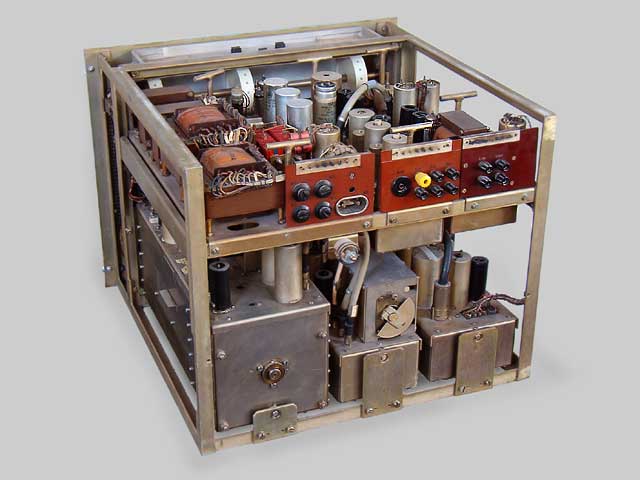
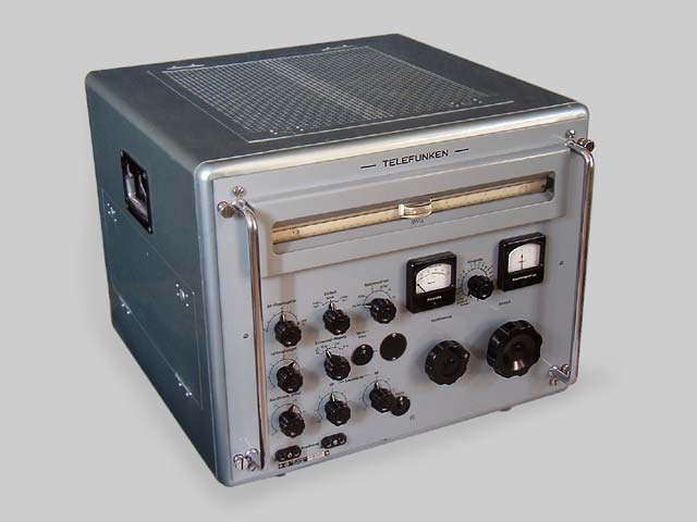
Rear view of the E 104 Kw/10
|
|
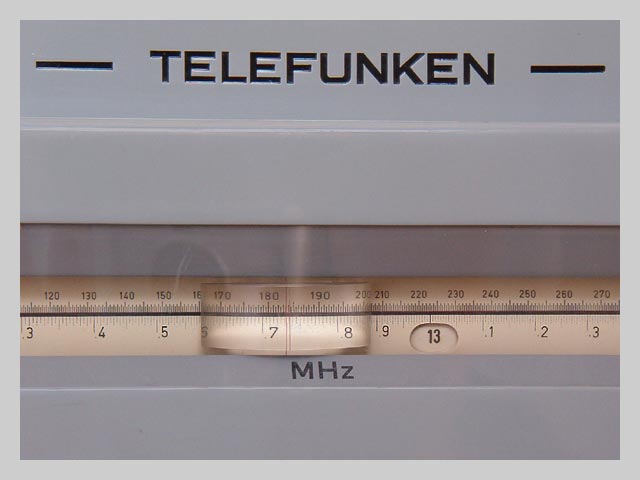
A detail of the front panel: the tuning dial
|
|
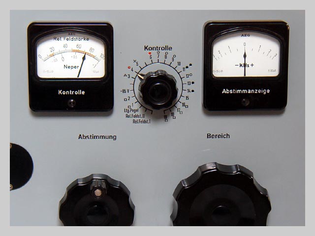
Another detail: tube checker and tuning meter
|
|
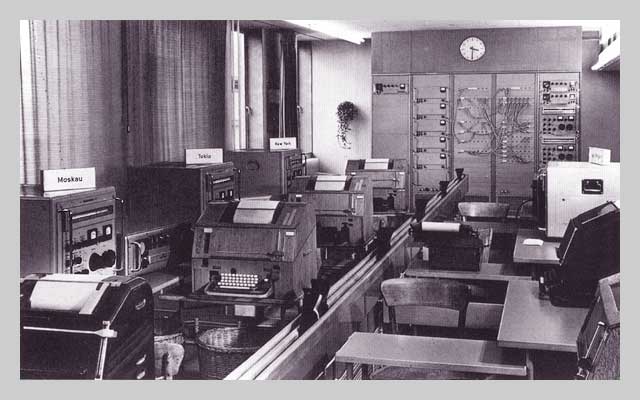
E 104 in use at Deutscher Wetterdienst Offenbach
|
|
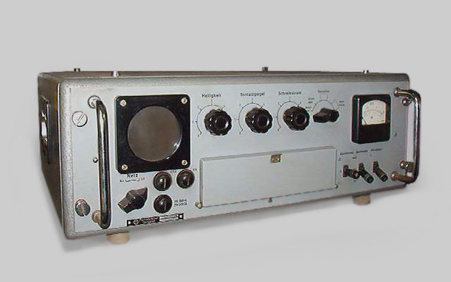
FSK converter Fs Tg 127
|