|
|
|
|
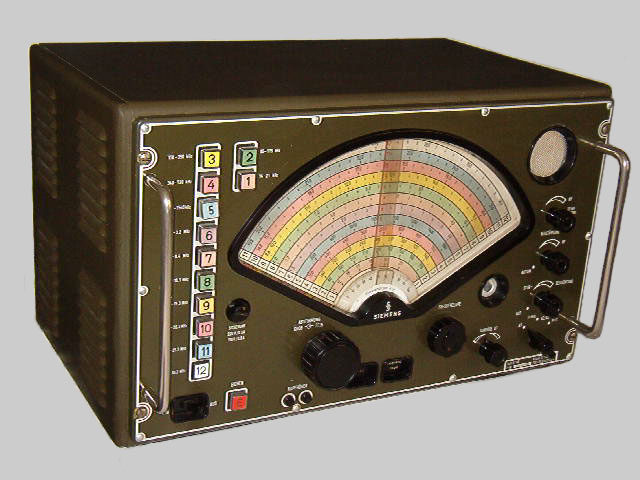
| General Coverage Communications Receiver |
| Double Conversion Superheterodyne |
| 17 Tubes + Semiconductors |
| Made in West Germany 1956 - 1971 |
| Specifications | |
| Coverage: | 14
21 / 85 175 / 170 350 / 340 730 / 720 1540 kHz
1.5 3.1 / 3.1 6.3 / 6.0 10.2 / 9.7 15.2 / 14.7 20.2 / 19.7 25.2 / 24.7 30.2 MHz |
| Modes: | AM/CW/MCW |
| Antenna Input: | SO-239 75 Ohms unbalanced |
| Sensitivity: | CW: 0.3 µV 6 dB S/N, AM: 8 µV (LF-MF), 4 µV (HF) 10 dB S/N |
| Setting & Read out: | 500 Hz |
| Selectivity: | 6.2/2.4/1.8
kHz 6 dB. In the 14 21 kHz and 85 175 kHz ranges 0.8 kHz 6 dB.
Formfactor -6/-60 dB: 1:2.8 at 6.2 kHz bandwidth. |
| IF: | 1st IF: 1080-1180 kHz, 2nd IF: 100 kHz |
| IF Rejection: | 50-70 dB, typically 70 dB |
| Image Rejection: | 40-80 dB |
| Audio Output: | 1.6 W/5000Ohms, 600 Ohms line |
| Voltages: | 110/125/220/250 V AC +/-10% 40-60 Hz, 100 W |
| Physical: | Cabinet Version: 550x350x380 mm, 35kg |
| Rack Version: 520x304x380mm | |
| Accessories: | FSE 2 or Teletron TG 440 for FSK, FSE 7 or Hellfax BS 110 for Fax |
| Features | |||
| - Headphone Jack | - Speaker | - Speaker Switch | - Line Out 600 Ohms |
| - BFO +/-3 kHz | - ANL | - AGC/MGC | - AGC 0.1/1sec. |
| - RF Gain | - Calibrator 100 kHz | - Dial Lamp | - Two Tuning Speeds |
| - Fine Tuning | - Break In Relay | - Semi Modular | - Rack Handles |
| Circuit Complement | |
| Tubes + Semiconductors: | 4x EF 93 (=6 BA 6), 3x EK 90 (=6 BE 6), 4x ECC 82 (=12 AU 7), 2x EAA 91 (=6 AL 5), 1x EL 90 (=6 AQ 5), 1x EM 34 (=6 CD 7), 1x 10⁸ C 1 (=0B 2), 1x 150 C 2 (=0A 2), selenium rectifiers in power supply. |
| Tuning: | Three ganged capacitors in RF circuits, three ganged capacitors in 1st variable IF-circuits. Continuos tuning by a knob (transmission 10:1 pushed and 160:1 pulled) via 1st oscillator. Alternatively above 1.5 MHz exact setting of 1st oscillator in steps of 100 kHz with calibrator for RF conversion to variable 1st IF (1180 to 1080 kHz), fine tuning via 2nd oscillator (1280 to 1180 kHz) for further conversion to 2nd IF (100 kHz). |
| Crystal: | 1x 100 kHz for calibration. |
| Dials: | Very big colorful coarse dial, first segment is fine tuning dial 100 kHz. |
| Comments |
| This model was designed for the marine market replacing the E 61, E 66a (LF, HF, 1948), E 303, E 305 and E 306 (all HF, 1952-1954). The E 310 was licensed as a class one receiver by Deutsche Bundespost. A standard receiver like competitor Hagenuk UE 12 on German ships. The twelve bands are selected by push-buttons on the left. Called "parrot cage" by the operators, referring to its colorful dial. Quite suitable for SSB reception using the product detector at 1.8 kHz bandwidth in CW mode. |
| Variants |
| The E 310b has a C-type antenna jack instead of the SO-239 jack. The E 566 is a very similar model, first with a dark green cabinet and front panel, later often light gray. |
| Additional Information |
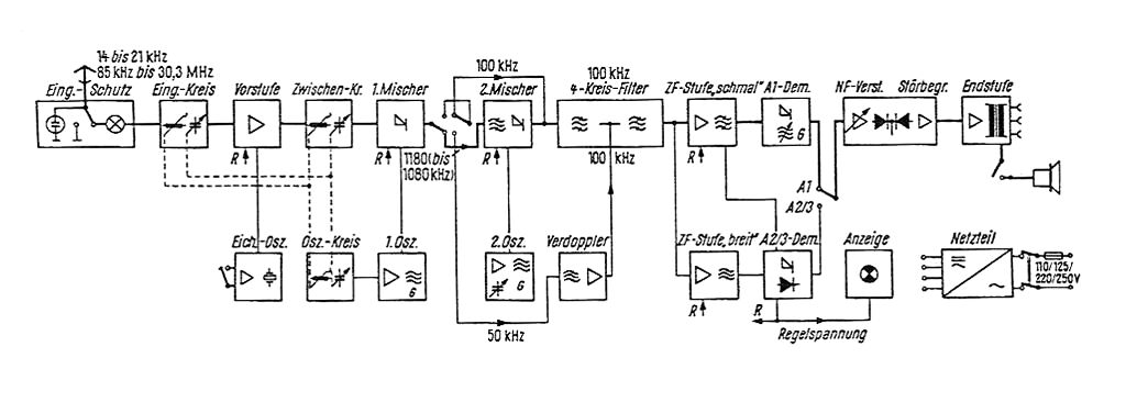
Block diagram of the E 310 (click to enarge).
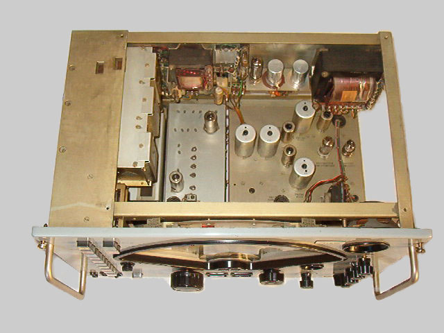
Top view of the E 310. The RF coil and capacitor deck is on the left hand side behind the push buttons.
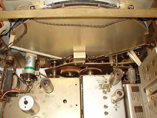
Back view of the dial. On the left hand side you see the magic eye (EM 35, it should actually be an EM 34).
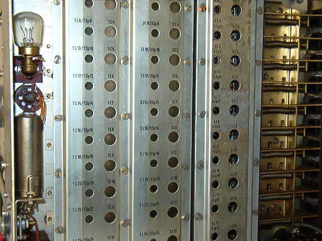
The RF coil and capacitor deck.